How does an operating system begin execution?
That sounds like an awfully complicated question, reserved for tech wizards of the highest order. But in reality, it’s a feasible question for a junior developer to answer if curious and motivated enough to do so. It’s only made complex by lack of documentation or ‘step-by-step tutorials’ around the topic, but fortunately, Dr. Nick Blundell conjured these fantastic lecture notes. For a more in-depth explanation of the topics covered in this article, I highly recommend checking it out.
To better understand the booting process this article will walk through the steps required to boot your own program off the B.I.O.S. and write the famous Hello World! type string on the screen. This is the first in a series of 2 articles. This current article’s purpose is to explain and show the fastest and easiest way to accomplish this goal.
The 2nd article will accomplish the same thing but lay out some more groundwork if one wants to go beyond this exercise and write a larger operating system.
The code:
All of the code referenced in this article is in this public GitHub repo.
1. The genesis
How does one even get code to run in the first place? A conventional application is started by the operating system. But in the barren pre-os land, you would rely on your system’s firmware to get things started.
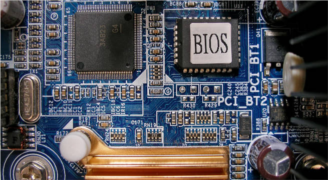
Firmware is software that is ‘baked’ into the motherboard of the PC, usually stored on what is called an EEPROM. It’s the first software that runs after the PC is powered on.
There’s no need to know everything about the PC’s firmware, the interesting part one would need to understand is the interface between the firmware and a bootable program, that is: the B.I.O.S. interface.
The B.I.O.S.
What is the B.I.O.S? Historically, it is the firmware of an IBM PC.
The IBM PC, released on August 12, 1981 by IBM had a substantial influence on the personal computer market. “Short for Basic Input Output System, the BIOS firmware came pre-installed on an IBM PC or IBM PC compatible system board. The specifications of the IBM PC became one of the most popular computer design standards in the world. The only significant competition it faced from a non-compatible platform throughout the 1980s was from Apple’s Macintosh product line, as well as consumer-grade platforms created by companies like Commodore and Atari.”[1] Due to its popularity and the nature of the market at the time, the interface of that original system served as a de facto standard for a long time in the Personal Computer market. In 1996, the BIOS Boot Specification was written by Compaq, Phoenix Technologies, and Intel.
In other words, the interface between the B.I.O.S firmware of the IBM PC and its operating system became a standard in the PC market. So much so, that one could assume that the firmware any Personal Computer has installed today implements this very interface.
It’s important to note that at the time of writing this article the BIOS Boot Specification is considered a legacy specification and U.E.F.I is the current standard specification for the interface between firmware and an Operating System today. Regardless, for compatibility reasons, the BIOS boot specification is still implemented by firmware vendors to this day.
Taking up the mantle
How do you get your code to run?
This next part involves writing a tiny bit of assembly code. If you’re not familiar with x86 assembly language or the concept of CPU instructions, there’s a brief explanation of assembly in the appendix of this article. For the curious, also see “How does a computer ‘see’ numbers?”.
The code for this exercise only contains 5 distinct x86 assembly instructions, 2 of which are only used once. Only a tiny bit of assembly code is required and soon enough it’ll be possible to use a higher-level language such as C, C++, Rust, Zig, or any language that compiles to native code.
Booting your code
The firmware that implements the BIOS interface looks to the first sector of the persistent data storage devices on one’s machine. This could be a hard disk, floppy disk, optical disc, USB drive, etc. This sector is also known as the ‘boot sector’ of a storage device. If the sector ends with the ‘magic number’ AA55h in hexadecimal, then the firmware identifies it as a bootable device.
A sector is the minimum storage unit of a storage device. “Each sector stores a fixed amount of user-accessible data, traditionally 512 bytes for hard disk drives (HDDs) and 2048 bytes for CD-ROMs and DVD-ROMs”[2]
Later on, we’ll be using a PC emulator to run this code and place it on an emulated hard disk. As such we’ll be placing the magic number at the 511th and 512th byte of the first sector of our virtual disk.
The BIOS then gives the option to boot from this storage device. If selected, all of the data from the boot sector gets copied over to address 0x7c00h, then the bios uses a jmp instruction to pass execution to that same address.
Thus, if we:
- Compile some code and write it into the boot sector of a storage device.
- Write the AA55h magic number at the end of the boot sector.
- Have the BIOS boot from that storage device.
The firmware will then pass execution over to our code. And there it would go. The CPU would now be executing our code.
The smallest bootable program
With that in mind, one could write the following program:
loop:
jmp loop
times 510 -($ - $$) db 0 ; Bootsector padding. Adding the AA55h
dw 0xaa55                ; magic number to the end of the 512
                         ; byte sector
Which is a classic endless loop.
In the assembly source file, the TIMES prefix along with the db pseudo-instruction and the $ and $$ tokens were used to pad out the binary with just enough 0’s and to add the magic number AA55h such that our code compiles to exactly the 512-byte size of the boot sector. Refer to the pseudo-instruction and the assembly language sections for further info on these.
Using a program to view the contents of a file in binary form we can see the data inside the boot sector:
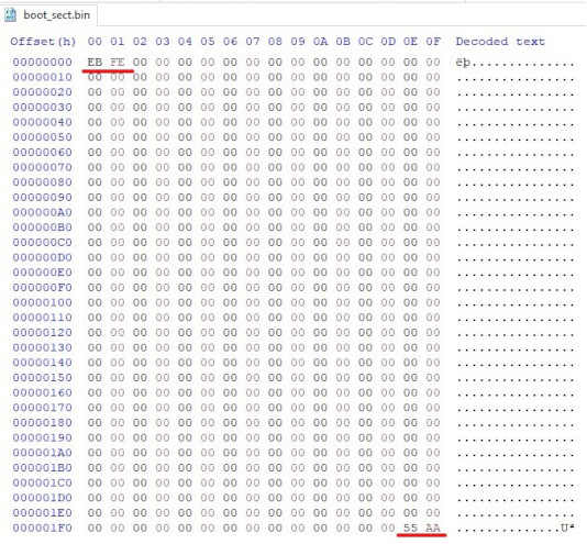
There are 2 chunks of data here worth talking about that I’ve underlined in red in the above image:
The 2 bytes at the beginning of the sector EB FE, represent the JMP instruction, along with its operand. Looking at this reference derived from the Intel® 64 and IA-32 Architectures Software Developer’s Manual, we can see the encoding for the x86 JMP instruction for a relative JMP with an operand that is 1 byte in size is EB. FE represents the number -2 that is encoded using the two’s complement method.
The 2 bytes at the end of the sector 55 AA represent the magic number that lets BIOS know this disk is bootable.
Endianness
Hold your horses, I thought the magic number was 0xAA55? It is, but in binary format it is flipped because of endianness. When a data element is larger than 1 byte, the question of: In which order should this sequence of bytes be read has to be asked. Left to right or right to left? “Danny Cohen introduced the terms big-endian and little-endian into computer science for data ordering in an Internet Experiment Note published in 1980”[3] The x86 architecture handles multi-byte values in little-endian format, whereby less significant bytes proceed more significant bytes, which is contrary to how we normally read numbers.
Ways of booting our code
At this point to boot off this code there are at least 3 options:
- Manually overwrite the first sector of a hard disk or USB drive with this data, and boot off our own machine.
- Use a virtual machine to simulate a computer, and use this code in the boot sector of a virtualized storage device represented by an .iso image file.
- Use a PC emulator to emulate a PC. Almost identical to option nr. 2, the main difference is that a virtual machine optimizes for performance by running instructions on the host machine, making use of specially designed hardware capabilities. This is called hardware-assisted virtualization. In contrast an emulator literally emulates every instruction through software. This results in a more portable, easier to debug but less performant simulation.
For the purposes of this article, we will go ahead with option nr 3.
Using a PC emulator

To emulate the PC, I’ve been using Bochs on a Windows 10 machine. Bochs, as mentioned on their website is a “highly portable open source IA-32 (x86) PC emulator written in C++, that runs on most popular platforms. It includes emulation of the Intel x86 CPU, common I/O devices, and a custom BIOS”.
The bochsrc configuration file
To set up Bochs, all one needs is a configuration file called bochsrc. Inside the installation folder for bochs, there is a file called bochsrc-sample.txt containing sensible default options for our emulator that I have copy pasted into the “/Part1” folder and renamed as bochsrc. In this case “/” references the root folder of the GitHub repo containing the code used in this article. The reason for this is that bochs first searches the current working directory for this configuration file, and in this case I execute bochs while my working directory is “/Part1”.
These options allow one to have bochs emulate a different processor type, change the amount of memory provided to the emulated machine, its sound driver, speaker, and so on. But all of this functionality is not needed for the simple purpose of writing a string on the screen as the provided defaults are sufficient.
The only configuration option we need to change is:
ata0-master: type=disk, mode=flat, path="30M.sampleto this:
ata0-master: type=disk, mode=flat, path="os-image.iso"This option defines the type and characteristics of an attached ata device. “Advanced Technology Attachment (ATA) is a standard physical interface for connecting storage devices within a computer”[4]. You might be familiar with SATA which stands for Serial ATA. I at least think of the SATA cables that one uses to connect modern hard disks or SSD’s to one’s motherboard.
Regardless, using this option we’re defining our virtual hard disk. The important part is the path property which leads to the file that contains the contents of the virtual hard disk device.
This is the file that contains our code which importantly, is located in the first 512 byte sector of this file. It could have any name you choose, I arbitrarily chose to call it os-image.iso.
Since the default configuration already defines the boot sequence to be from disk:
boot: diskThis is all that needs to change for the firmware emulated by Bochs to discover and boot off our virtual hard disk.
Let’s run the smallest program on the emulator
Everything is set up and ready to go. All we need to do is compile the smallest bootable program, attach the code to the first sector of an image file, call that file os-image.iso, and run bochs.
I am using a Windows 10 machine, on which I’ve installed Cygwin and nasm. Nasm, which stands for the Netwide Assembler (NASM) is an assembler for the x86 CPU architecture. These are the commands I used to compile the code and start Bochs:
nasm smallest_program/boot_sect.asm -f bin -o bin/smallest_program.bin
cat bin/smallest_program.bin > os-image.iso
truncate -s 10485760 os-image.iso
"C:/Program Files/Bochs-2.7/bochs.exe"
Let’s walk through each command used:
The first command compiles our assembly code. Notice that the -f bin property was set. This is to inform nasm to output pure binary code. As opposed to its default behaviour which is to output an object file, meant to be further processed by a linker. On Windows, this further processing would result in an executable with the PE format (The familiar .exe files). Windows executables have a lot more data inside them besides just machine code and are meant to be loaded by an operating system. Since we are only interested in the machine code, the -f bin property is used.
The second command uses a GNU coreutil from Cygwin, called cat. Cat copies the files given to it to standard output, and our pipe redirects our standard output to a file called ‘os-image.iso’. Ultimately this just renames our binary file to ‘os-image.iso’. Why complicate things and use cat for this purpose? That is, since later on cat can be used to ensure that our boot sector is the first sector in our image, and it’s useful to acquaint ourselves with it early on.
The third command uses a GNU coreutil from Cygwin, called truncate. This pads our file with the value 0 to our file until it reaches a certain size. In this case, 10485760 bytes which is equivalent to 10 megabytes. This is to satisfy Bochs since it doesn’t allow an ATA device to only have 512 bytes of data.
Run all of these commands and …
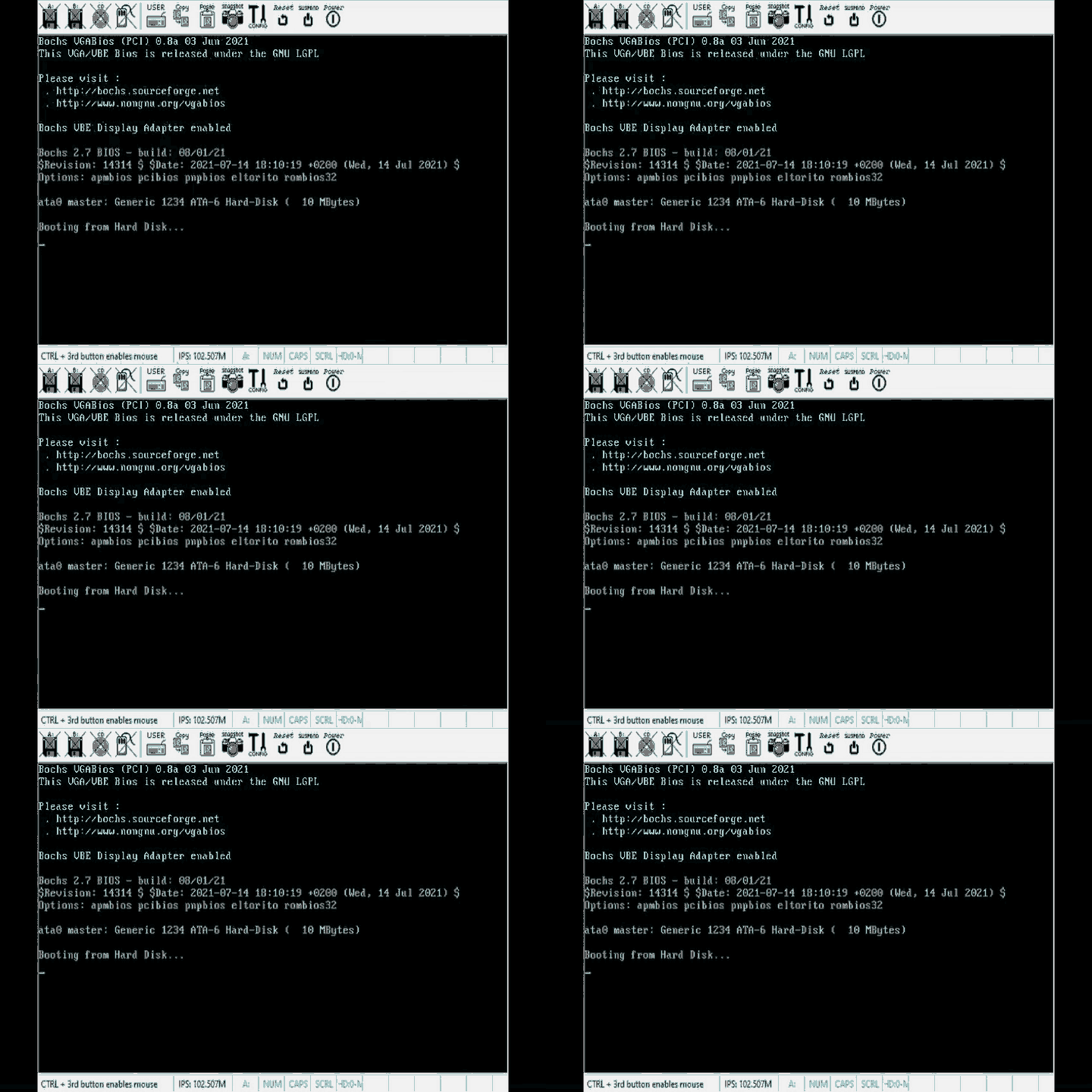
There it is, the simplest possible program, booted off the bios in all its glory. Notice that this GIF looks like it was recorded by a camera from the 1960’s. That’s because I chose to export the gif with only 8 colors to save on the memory used by this page.
Writing Hello World on the screen from a bootable program
We’re so close to our goal. All we need is a way to write to the screen. Fortunately, the B.I.O.S interface describes a function just for that goal.
Interrupts
The B.I.O.S interface makes its routines available via interrupts. Interrupts are a processor feature that allows you to temporarily halt the CPU from what it’s doing and have it jump execution to what is called an ISR (Interrupt Service Routine), before resuming execution of the code it was at before the interrupt.
Interrupts are a vital feature of processors, as they can be triggered both by software like we are now, and by hardware. This is the feature that allows computers to react to keys being pressed on a keyboard for example.
In theory, we could scan memory to find the B.I.O.S routine we’re interested in and manually jump execution to its address, but to keep code easy and portable across multiple machines B.I.O.S provides us with a handy ISR already connected to the intrerrupt vector.
As mentioned in Dr. Nick Blundell lecture notes: “Each interrupt is represented by a unique number that is an index to the interrupt vector, a table initially set up by BIOS at the start of memory (i.e. at physical address 0x0) that contains address pointers to interrupt service routines (ISRs).
…
So, in a nutshell, BIOS adds some of its own ISRs to the interrupt vector that specialize in certain aspects of the computer, for example: interrupt 0x10 causes the screen-related ISR to be invoked, and interrupt 0x13, the disk-related I/O ISR. “.
Writing a character on the screen
BIOS makes use of the ah register to determine which routine we want to invoke. For the routine related to printing characters on the screen, it requires ah to contain the value 0xeh.
The screen-related ISR requires the character to be printed to be inside register al. The ISR we need is invoked by index 10 in the interrupt vector, and we’ll use the int instruction to invoke a software interrupt which will execute the ISR that’s currently attached to index 10.
mov ah , 0x0e
mov al, 'A'
int 0x10 ; Invoke software intrerrupt to print al
         ; which contains the character 'A'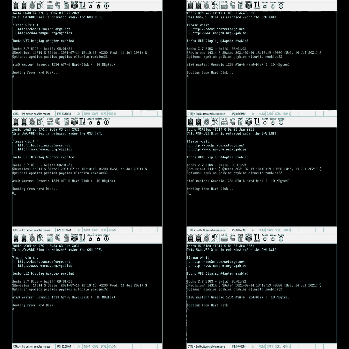
Hello Boot!
With this information, we could technically just write this code and be done:
mov ah , 0x0e
mov al, 'H'
int 0x10
mov al, 'E'
int 0x10
mov al, 'L'
int 0x10
mov al, 'L'
int 0x10
mov al, 'O'
int 0x10
mov al, ' '
int 0x10
mov al, 'B'
int 0x10
mov al, 'O'
int 0x10
mov al, 'O'
int 0x10
mov al, 'O'
int 0x10
mov al, 'T'
int 0x10
mov al, '!'
int 0x10
But in the interest of making the code a bit cleaner, we’ll write a little loop to do this work:
[org 0x7c00]
mov bx , HELLO_WORLD_STRING
mov ah , 0x0e ; int 10/ ah = 0eh -> scrolling teletype BIOS routine

print_string_loop:
; Checking if we reached the end of the C-style string
mov cl, [bx]
cmp cl, 0
je print_string_end

;Print the character currently pointed to by bx
mov al, [bx]
int 0x10 ; print (al)

inc bx ;Increment bx to point to the next character in the string
jmp print_string_loop

print_string_end:
jmp $

HELLO_WORLD_STRING db "Hello Boot!" , 0

times 510 -($ - $$) db 0
dw 0xaa55
This code introduces a new directive, org, some new instructions cmp, je, inc, and what nasm calls a ‘pseudo-instruction’ db. Let’s explain each one of them one by one.
The org directive
[org 0x7c00]This directive lets nasm know that this code will be loaded at address 0x7c00, which is where the BIOS always loads our boot sector.
This is important because we reference the label HELLO_WORLD_STRING in our code. That label will be replaced by a memory address, and the assembler wouldn’t know where in memory it’s going to be without this directive.
Let’s try compiling the code and then disassembling it with and without the org directive to see what happens (I will be using the ndisasm utility executable that comes with NASM to disassemble the code after compilation):
With the org directive:
00000000  BB157C            mov bx,0x7c15
00000003  B40E              mov ah,0xe
00000005  8A0F              mov cl,[bx]
00000007  80F900            cmp cl,0x0
...
Without the org directive:
00000000  BB1500            mov bx,0x15
00000003  B40E              mov ah,0xe
00000005  8A0F              mov cl,[bx]
00000007  80F900            cmp cl,0x0
...
As can be seen, without the directive the code will try to fetch data from address 15, which is not where the Hello World string of bytes will end up. Since the string of bytes is inside our 512-byte boot sector, it’ll get copied over along with our code to address 0x7c00. Only by using the directive can the assembler correctly resolve our label to the address where the string of bytes is.
The db pseudo-instruction
We introduce what nasm calls a ‘pseudo-instruction’ db. According to nasm’s reference manual “Pseudo-instructions are things which, though not real x86 machine instructions, are used in the instruction field anyway because that’s the most convenient place to put them”
db is used to declare initialized data in the output file, where the name stands for data byte. In other words, we’re simply declaring some data, and in our binary output file, we’ll literally just have the ASCII codes representing the “Hello World” characters followed by a 0. The 0 is important so that our loop knows when we reach the end of the string.
CMP and JE
The cmp instruction compares the next character with 0 so that we know when the end of our string is reached. What the instruction does is set a register flag EFLAGS according to the results. We’re interested in the ZF flag inside EFLAGS, which is going to be set to 1 if the two operands supplied to CMP are equal. The je stands for Jump if Equal, and all it does is jump to the specified address offset if the ZF flag is set to 1. You can see how CMP and JE are working together here since CMP is setting the ZF flag (along with other flags that we’re not interested in here) which then JE instruction depends on. Together they cause the code to jump to the print_string_end label when the next character is 0 which indicates that we’ve reached the end of the string.
The [] notation
This notation of surrounding a register with square braces ‘[bx]’ literally means: take the value pointed to by the address in the bx register instead of the actual value of the bx register which is an address. If we were to write the same code without the square brackets, instead of moving the character that bx points to into cl, we’d move the address that the character is at into cl.
INC
The inc instruction increments the value stored at the bx register by 1, such bx points to the address of the next character in the string.
Finally…
Then we run the same commands as we did with the smallest bootable program and …
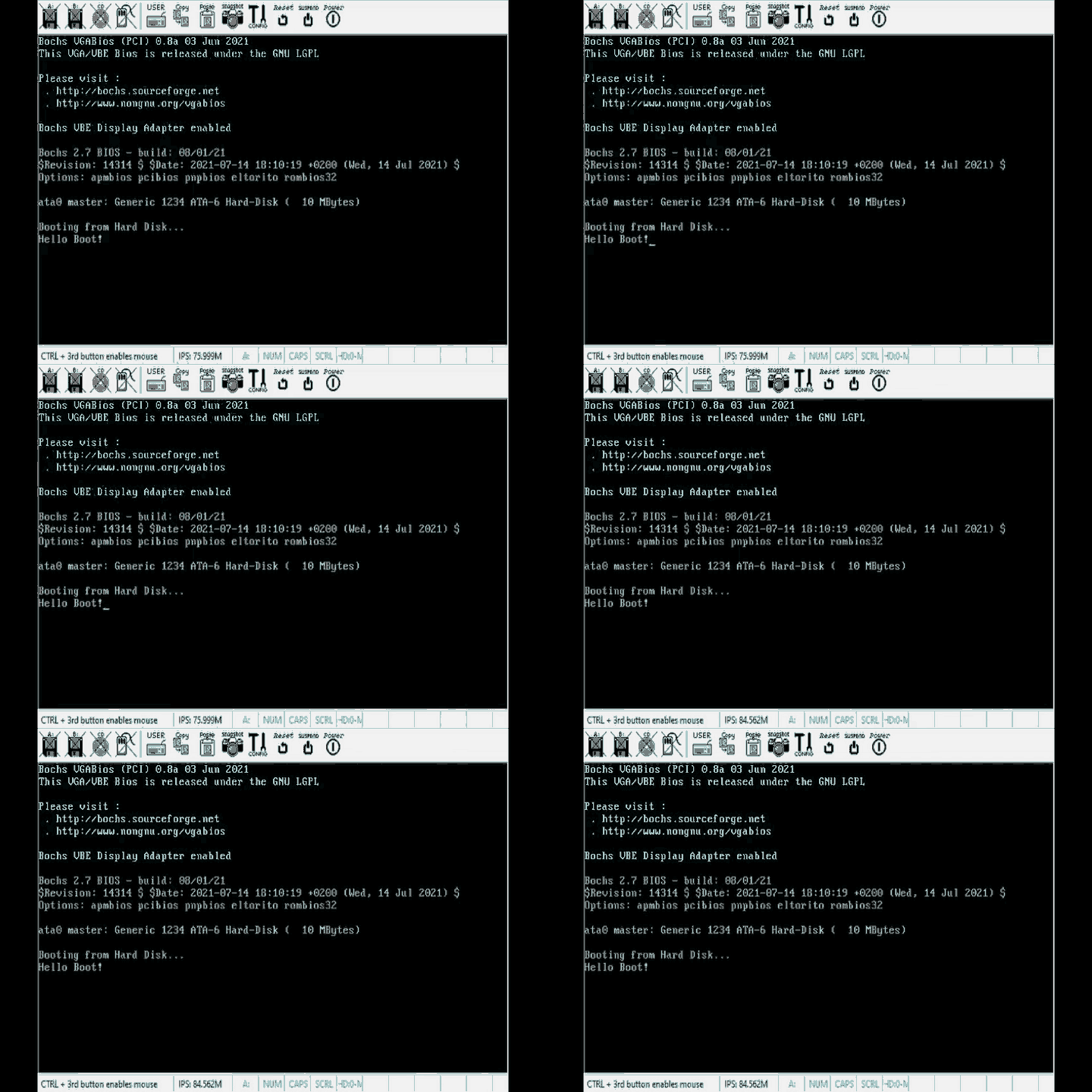
There it is! We’re done.
Conclusion and part 2 …
Phew, that was a lot more work than:
cout << "Hello World!";But hopefully, it was worth it. I learned so much from asking this question and delving into this topic, even learning a tiny bit of assembly, a bit about electronics and computers along the way. Some might say this is a pointless exercise, why reinvent the wheel? But I found it fun and I was simply curious to know how an operating system starts executing code. I do find that I have a better understanding of how user-space programs work, and I scratch my head a bit less when reading about C++ features that aren’t related to algorithm logic, but have more to do with how the code compiles internally.
C/C++ and systems languages in general have a range of features that can only be understood from the bottom up. For example when declaring the calling convention of a function. Whatever algorithm the function implements will work the same way, but the underlying machine code will be different. Another example is move semantics in C++. One will occasionally stumble across keywords and language features such as these in C/C++ source code and they’re impossible to understand without a bit of low-level diving.
What’s to come
This is the first article in a series of 2. While the original inquiry is answered, still many questions remain:
- What if we want to have code larger than 512 bytes?
- How do we compile and use a higher-level language like C++ in this pre-os environment?
- How did the BIOS create the function to write the characters on screen? More generally, how do you write code that interacts with devices(a.k.a drivers)?
- Is A.I. going to take over all software engineering jobs in the next 10 years?
These first 3 questions and more will be answered in the second part of this article series…
Appendix
Assembly language
What is the Assembly language? First of all, there is no one single assembly language. Every CPU has its own instruction set architecture, which comes with its own assembly language. In this post, we’ve been using x86-assembly, which compiles to instructions for the x86 family of instruction set architectures.
An instruction set architecture
An instruction set architecture, is in some sense the information most relevant to a software engineer since it defines what instructions a CPU implements. It does not describe how, internally these instructions are to be implemented, but what they are and what they functionally do.
From Arm’s website: “An Instruction Set Architecture (ISA) is part of the abstract model of a computer that defines how the CPU is controlled by the software. The ISA acts as an interface between the hardware and the software, specifying both what the processor is capable of doing as well as how it gets done.”
When mentioning the x86 instruction set, one refers to a whole family of instruction set architectures. All of which have a large array of instructions in common. While basic instructions like MOV, JMP, CMP, and JE are shared amongst this family of ISAs, some instructions are more specific to an individual CPU. If one wanted to target a very specific ISA with nasm, the CPU directive would be used in the assembly source file.
Assembly is a language in which each statement corresponds to an instruction. One large advantage of it over just writing machine code by hand is that you can refer to instructions by their name, rather than a dull number. It’s a lot easier to associate JMP with the functionality of having the processor jump to a new address, rather than associating the number 0xEB to that functionality.
Moreover, instructions with very similar functionality have a different encoding based on factors such as operand size. For example, the JMP instruction’s encoding changes from 0xEB to 0xE9 if the operand used is 2 bytes long instead of 1.
| Opcode | Instruction | Op/En | 64 bit mode | Compat/Leg mode |
|---|---|---|---|---|
| EB cb | JMP rel8 | D | Valid | Valid |
| E9 cw | JMP rel16 | D | N.S | Valid |
Assembly removes the mental overhead of having to switch instructions based on operand size and other factors and allows us to just use JMP in both scenarios since the compiler will figure out what opcode should be used.
Moreover, there are other features in assembly languages, such as labels, or the ability to express data.
loop:
jmp loop
times 510 -($ - $$) db 0 ; Bootsector padding. Adding the AA55h
dw 0xaa55                ; magic number to the end of the 512
                         ; byte sector
As can be seen in the smallest bootable program, the label ‘loop:’ was defined and used as an operand to the jmp instruction. The assembly compiler determined at compile time the value of the operand to the JMP instruction such that execution would jump to where the loop label would be.
What are these $ symbols though? From nasms reference manual: “NASM supports two special tokens in expressions, allowing calculations to involve the current assembly position: the $ and \(tokens. $ evaluates to the assembly position at the beginning of the line containing the expression; so you can code an infinite loop using JMP $.\) evaluates to the beginning of the current section; so you can tell how far into the section you are by using ($-$$)”
Without assembly, there would be much mental overhead in figuring out the exact nr of bytes one would want to jump to in order to get behind where the loop label would be.
Not to mention you’d have to manually apply the two’s complement method to a number to figure out its integer representation.
By this point, it’s clear that as low-level as it is, assembly does a lot of work to simplify the creation of programs.
References
[1] https://en.wikipedia.org/wiki/IBM
[2] https://en.wikipedia.org/wiki/Disk_sector
[3] https://en.wikipedia.org/wiki/Endianness
[4] https://www.techopedia.com/definition/2142/advanced-technology-attachment-ata
