I still remember when I started programming the confusion I felt trying to make a real-world connection to how computers worked. Computers just do math everyone says. How is that possible? How can a physical thing be aware of and manipulate numbers?
A computer doesn’t ‘see numbers’ since numbers are an abstract mathematical concept. The computer interprets electric signals on a bus. A bus in practice is a bundle of wires that transmits electric signals, but the more academic, abstract definition is: “A bus (historically also called data highway or databus) is a communication system that transfers data between components inside a computer, or between computers” [1].
It so happens that, as humans, we can make a one-to-one association between a number and a signal on a bus. This is because every number can be converted to base 2, which can then be associated with a signal. Let me explain:
The anatomy of a number
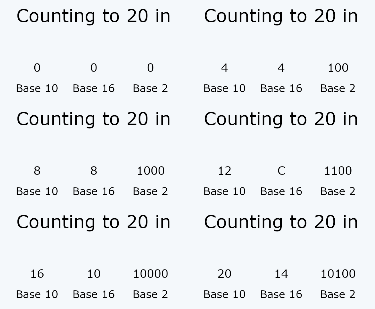
Every number has a property that is called a base. The base of a number represents the amount of symbols used to represent it. Conventionally we use 10 different symbols to represent a number: 0, 1, 2, 3 …, 9. And as such we say that our numbers are represented in base 10, also known as a decimal base.
We can, however, use more or less symbols to represent the same number value. For example, if we use base 16, we have 6 extra symbols that allow us to go all the way to 15 with a single symbol. The lazy way to find more symbols is to use the letters of the alphabet. So counting to 15 would look like this: 0, 1, …, 9, A, B, C, D, E, F.
Crucially, we could also use a smaller base to represent the same number value. Binary, or base 2 only uses the symbols 0 and 1. This is crucial to understand and its relevance will be shown a bit further in this article. I’m sure you must’ve heard the phrase before: “Computers only see zeros and ones”.
Why would we do this though?
What is the utility of being able to represent the same number value with multiple bases?
In the case of the binary representation, the reason is because we can associate an electric signal on a bus with a number. What does that mean? This is easiest to understand with an example:
For a more detailed explanation of how number bases work, see this page from LibreTexts.
How does the processor ‘see’ a number?
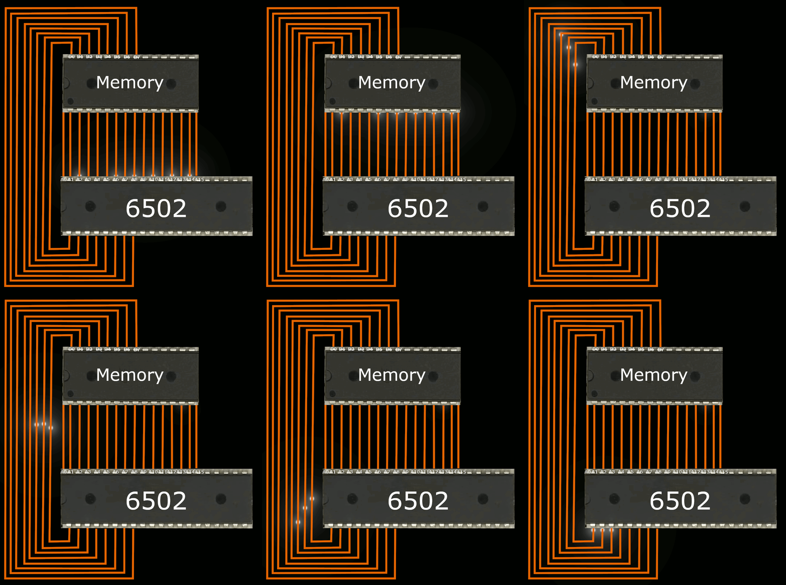
For example, let’s assume we’re programming for the 6502 microprocessor. This processor or variants of its design were used in the Atari2600, the Apple II, the NES (Nintendo Entertainment System), Commodore 64 and many other machines.
In the above animation, the 6502 is doing a memory read from address 21828. At this point in time, the memory module contains the value 7 at this address. These are completely arbitrary values chosen for this example.
I am referring to the address by stating a number, but what’s happening at the hardware level is that the CPU is sending an electric signal to the memory module. The decimal number 21828 is equivalent to 0101 0101 0100 0100 in binary. And decimal 7 is 0000 0111.
It’s a bit hard to see in the above animation, but each individual wire from the bus is labeled according to the bit it represents in the ‘number’. If you look closely you will notice the A0, A1, A2, … A14, A15 labels for the wires on the address BUS, and the D0, D1, … D7 labels for the wires on the data BUS.
The electric signal that is sent on the 16-wire BUS has the wires representing bit number 2, bit number 6, bit number 8, bit number 10, bit number 12, and bit number 14 contain a voltage that is high enough such that they are considered to be ‘turned on’ by the memory module, while every other wire’s voltage is low enough to be considered as ‘turned off’.
Similarly, in response, using the data BUS, the signal sent by the memory module has the first 3 wires containing a high voltage, while all the other wires contain a low voltage, representing number 7.
Since given one number we can find a single representative signal for it and vice versa: given a signal we can find a single representative number for it, the two can be thought of as being equivalent.
Summary
So in practice, a processor is an electronic circuit that interprets electric signals. These signals can be associated with binary numbers. And a binary number is still a number like any other. It can be converted to a more familiar decimal base. The computer cannot see ‘numbers’, but in spoken and written language people refer to the electric signals by using numbers.
In this example, we’re doing a memory read, but the processor can do many other operations on these signals including mathematical ones such as addition and subtraction.
Note that the above gif is not 100% accurate to how a 6502 would be connected to a memory module. I left a few things out and took the liberty to rearrange the 6502’s pins to make animating the gif easier. That is, the address A0, A1, … A15 pins are not literally located at the front of the CPU. Animating the 21 frames for this GIF would be a lot harder if I had to draw the signal for wires of different lengths. Also, in a real-world scenario, there is an extra pin not shown in this gif that indicates whether the CPU is reading from or writing to memory.
For a 100% accurate depiction of how the 6502 reads from and writes to memory, this series of videos by Ben Eater shows a how to write a program to print out Hello World from a 6502 microprocessor. This is a fantastic resource that made things much more intuitive for me. I highly recommend checking it out if you’re interested in understanding what was explained in this section more deeply.
On a more abstract note, the concept of computing itself is technically not related to electricity, but electricity is an appropriate medium to use for its implementation. A fascinating video that is tangentially related to this topic is I Made A Water Computer And It Actually Works by Steve Mould. Featuring an addition gate that uses water instead of electricity to perform an addition operation.
Extra: CPU instructions and memory
The previous example shows a memory read, but what is memory?
Memory can be thought of as an electric circuit whose main purpose is to store data. Each data element in memory has a corresponding address and value. Both the address and value are just ‘numbers’ or as we discussed, signals. The size of the address is represented by the architecture of the CPU. On an 8-bit architecture the address is an 8-bit number, on a 16-bit architecture it’s a 16-bit number, and as you might guess in current times on a 64-bit architecture, the address is a 64-bit number. The value however is always an 8-bit value. Or at least it has been on every modern computer architecture since 1978.
CPU Instructions
CPU instructions are simply ‘numbers’ or ‘signals’ stored in memory. The CPU has a special register called a ‘program counter’, sometimes known as the ‘instruction pointer’ holding the address of the next instruction to be executed.
A register is a container inside a CPU that stores some data. Unlike memory, the register is physically inside the CPU and as a result access to registers is much faster than access to a memory address.
What the CPU literally does is look at the address specified in the program counter, fetch the next instruction from memory at that address, increment the program counter by the length of the instruction fetched, execute the instruction, and repeat.

The article Hello Boot! Writing a string on the screen after booting off the B.I.O.S. (1/2) features a very simple infinite loop program written in x86 assembly.
To understand the nature of instructions, we’re interested in the compiled version of the program containing the machine code:
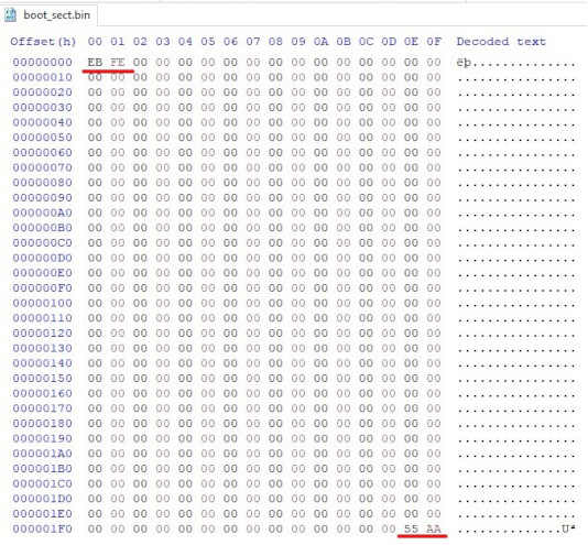
It can seen in the image that the program compiles to 2 numbers written in base 16 (hexadecimal) EB and FE. The 2 other numbers 55 and AA can be ignored as they represent something else entirely. Their meaning is explained in the original article.
EB represents the JMP instruction and FE its operand in the x86 instruction set architecture. Looking at this reference derived from the Intel® 64 and IA-32 Architectures Software Developer’s Manual, it can be seen in the first column that the opcode for the JMP instruction with an 8-byte operand is EB, just like in our code.
| Opcode | Instruction | Op/En | 64 bit mode | Compat/Leg mode |
|---|---|---|---|---|
| EB cb | JMP rel8 | D | Valid | Valid |
FE is the operand to the instruction and is the hexadecimal representation of -2. Why is -2 equal to FE ? There are multiple ways of representing signed integers, but the Intel® 64 and IA-32 Architectures use the two’s complement encoding method.
On the concept of encoding
More generally, any information at all can be encoded into a number. If I wanted to I could create an encoding standard where I refer to the sweater I’m wearing as number 1, my coffee cup as nr 2, and so on.
As for a more practical example, there’s the ASCII encoding standard abbreviated from American Standard Code for Information Interchange which encodes text characters. For example, the character ‘A’ is represented as nr. 65 in decimal.
Since computers can only really store numbers we rely on encoding methods that humans define and agree on to represent any kind of data numerically. In this case, we want to encode negative numbers, and while there exist many methods to do so, one of the most common is the two’s complement method which happens to be used by the Intel® 64 and IA-32 Architectures.
Thus that code does a relative jump -2 bytes from the address of the next instruction. Since our code is 2 bytes long, that jump will lead the program counter right back to our JMP instruction, resulting in an endless loop.
References
[1] https://en.wikipedia.org/wiki/Bus_(computing)
